ELECTRICAL DESIGN
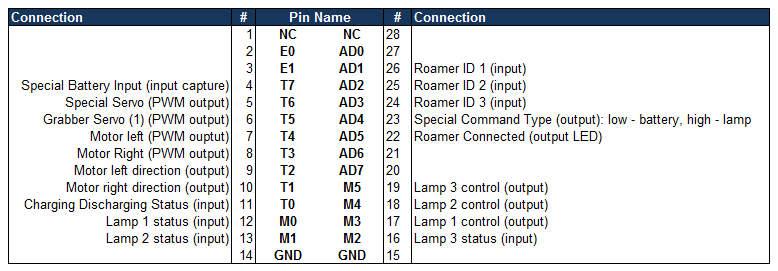
Pinouts for C32 (Roamer)
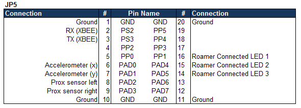
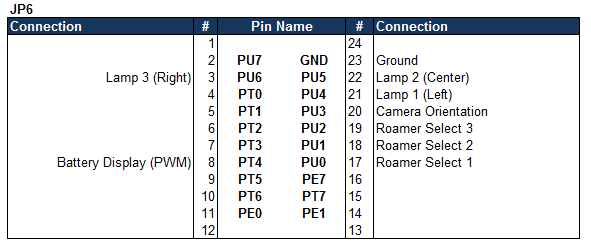
Pinouts for E128 (POD)
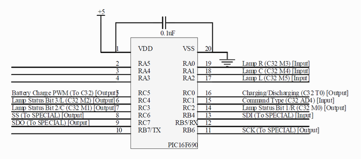
Pinouts for PIC16F690 (ROAMER)
|
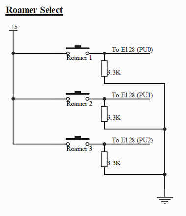
Roamer Select Buttons (POD)Three simple button circuits with 3.3K pull-down resistors were used to identify which ROAMER number we wanted to connect with. Similar switch circuits were utilized on the ROAMER side to identify which number it was.
|
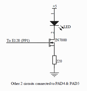
LED Circuits (POD)To indicate a connect (to a ROAMER), an N-channel MOSFET (2N7000) was used to switch the LEDs on (if connected) and off (if not connected). When given 5V (logic high from the E128), the LED turns on. That of course means when the signal is logic low (0V), the LED is off.
|
|
|
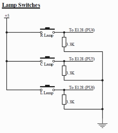
Lamp Switches (POD)Three switches, similar to those for the ROAMER select, were used to turn on/off the lamps on the SPECIAL.
|
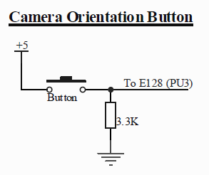
Camera Orientation Button (POD)A simple button with a 3.3K pull-down resistor was used to change the camera orientation (facing forward or facing backwards - 180 degree change).
|
|
|
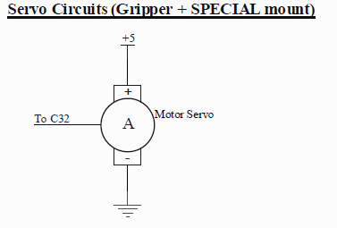
Servo Circuit (ROAMER)Two features on the ROAMER utilized the servo circuit: the gripper and the SPECIAL mount. The servo opened/closed the gripper and turned the orientation of the SPECIAL mount.
|
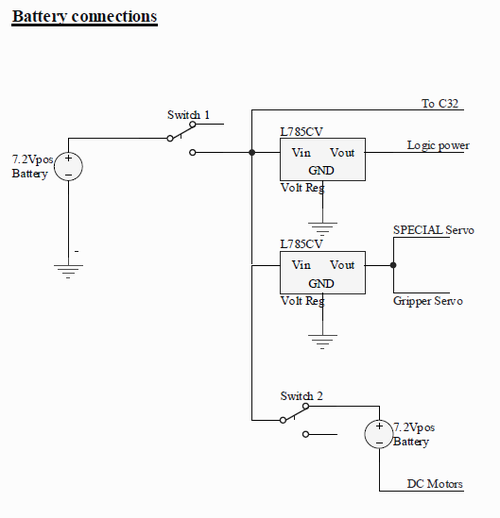
Battery Connections (ROAMER)Two 7.2 NiCad rechargeable batteries were used to power the ROAMER. One battery powered the C32, logic devices, and the 2 servos while the other was connected in series to the first to power the ROAMER's motors at ~15V.
|
|
Motor Driver Circuit (ROAMER)
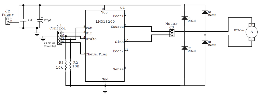
To drive the ROAMER motors (wheels for movement), we utilized 2 LMD18200, one for each wheel, with drive-coast PWM operation. The brake pin was held low and direction pins were toggled to control direction of movement.
|
|
Pod power consumption
E128:
Run supply current = 65 mA
Servo:
Typical current = 30 mA
Proximity Sensors (x2):
Average dissipation current = 15 mA
Accelerometer:
Normal operating current = 500 uA
XBEE:
Transmit current (typical) = 45 mA
Idle/Receive current (typical) = 50 mA
Button LEDs:
5V drop across 2N7000 and 220 ohm resistor
2N700 Rds(on) = 1.7 ohm (typical) for Vgs = 5V, Id = 50 mA
2.7 V typical voltage drop across LED
(5-2.7)V/221.7ohm = 10.2 mA
Total Power Consumption: A linear voltage regulator was used, so input voltage is multiplied by total current (excess voltage lost as heat). A 7.2 V, 1500 mAh battery was used.
Total Current = 65 + 30 + 15*2 + 0.5 + 50 + 10.2 = 185.7 mA
Total Power = 185.7 mA * 7.2V = 1.34 W
Required Battery Capacity = 185.7 mA* 8 hrs = 1486 mAh < 1500 mAh
